NexCharge: 10A Smart Auto Cut-Off Battery Charger
Friday, August 28, 2026
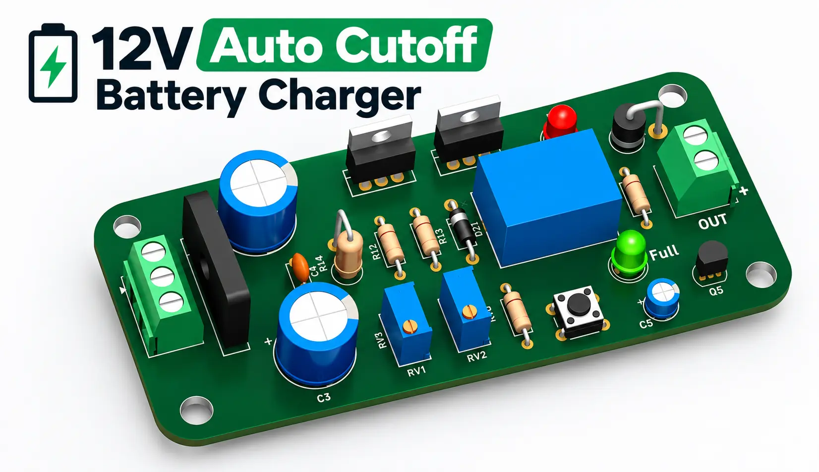
A robust, high-current linear battery charging platform engineered specifically for 12V lead-acid and SLA batteries. Designed with an active voltage-sensing feedback loop, the system delivers up to 10A of regulated charging current while automatically isolating the battery bank via an electromechanical relay upon reaching full charge (~14.4V). This prevents overcharging, reduces electrolyte degradation, and extends battery lifespan without relying on complex software stacks.

Key Technical Specifications
- Charging Topology: High-current linear regulator with power transistor bypass.
- Target Chemistry: 12V Flooded, Sealed Lead-Acid (SLA), Gel, and Deep-Cycle batteries.
- Continuous Output Current: Up to 10A with appropriate heatsinking.
- Cut-Off Mechanism: Relay-based automatic latching disconnect at high-voltage threshold.
- Threshold Adjustment: Dual multi-turn precision trimpots for independent upper cut-off and hysteresis calibration.
- Diagnostics & Metering: Dual-color LED status indicators (Charging vs. Full) alongside a real-time digital voltage/current panel display.
- Protection Systems: Reverse-EMF flyback diode clamping, thermal heatsink dissipation, and reinforced high-current trace architecture.
Circuit Architecture & Working Principle
1. Rectification & Bulk Filtering
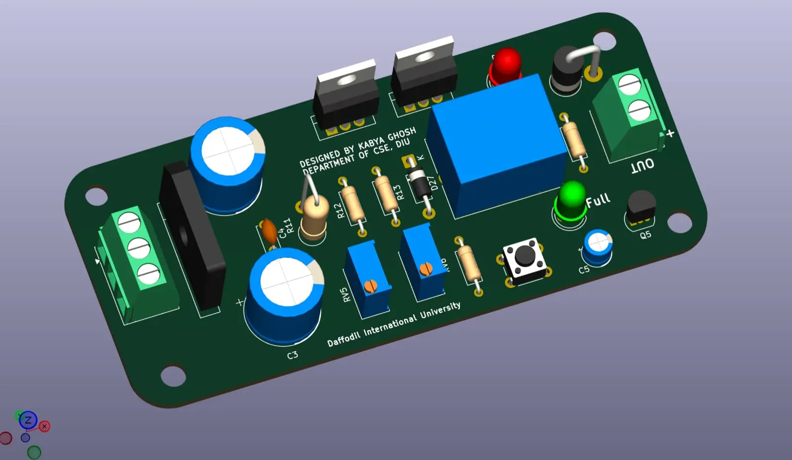
AC input from a center-tapped or standard secondary step-down transformer enters via a heavy-duty screw terminal block. It feeds into a bridge rectifier IC that converts AC to pulsating DC. High-capacity electrolytic reservoir capacitors smooth the rectified waveform into a stable DC rail with low ripple under heavy 10A draw.
2. High-Current Regulation Stage
Voltage regulation is established using an adjustable linear regulator IC combined with TO-220 power bypass transistors mounted on extruded aluminum heatsinks. The regulator maintains the float/boost voltage setpoint, while the power transistors handle the bulk of the 10A charging current to prevent thermal overloading.
3. Automatic Cut-Off & Latching Circuit
A dedicated BJT transistor sensing stage continuously samples the battery terminal voltage. Once the battery reaches full charge capacity:
- The sensing circuit energizes the 12V SPDT relay coil.
- The relay contacts switch, physically breaking the charging loop.
- The green "Full" LED illuminates, signaling charge completion.
- An onboard tactile push button allows manual reset/re-engagement of the charging cycle when required.
Hardware Prototyping & High-Current Assembly
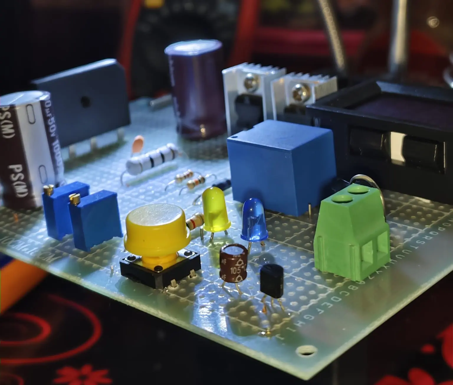
Before manufacturing custom production boards, the circuit was validated on a high-grade 10cm × 15cm FR-4 prototype perfboard.
Reinforced Current Rails
Because standard perfboard copper pads cannot safely conduct sustained 10A current without overheating, the underside power traces were reinforced with heavy-gauge solid copper bus wire soldered directly across the high-current paths. This minimizes trace resistance ($I^2R$ power loss) and guarantees structural thermal stability under continuous peak loads.