Back to PortfolioEmbedded Systems
DIY CNC Pen Plotter: Technical Documentation
Sunday, September 13, 2026
Project Overview
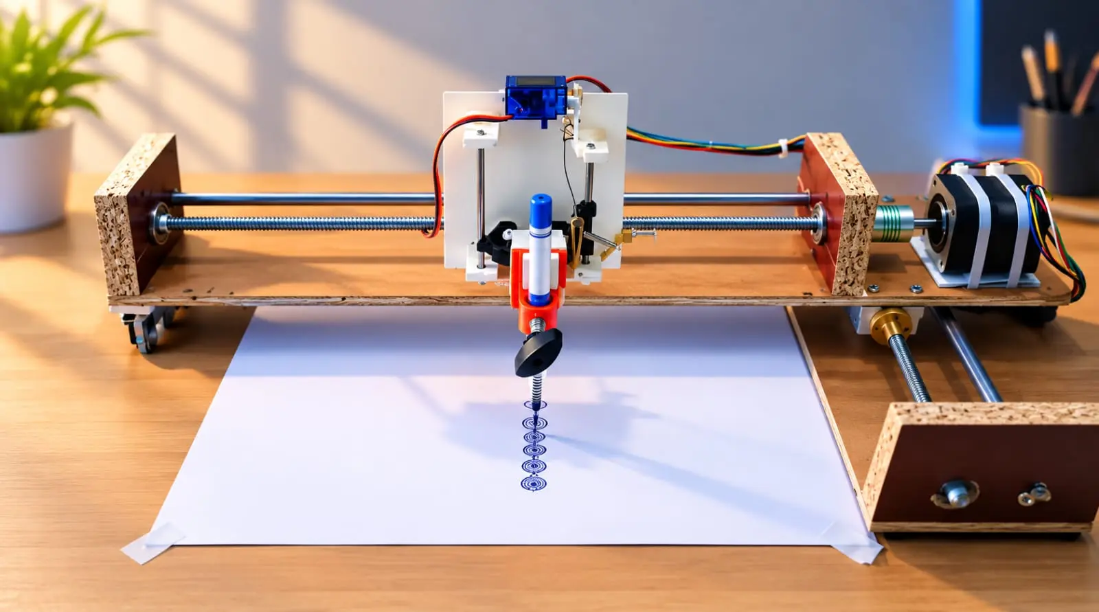
This documentation details the construction and software configuration of a 2-axis DIY CNC Pen Plotter. The system is built on an MDF/particle board base with linear guide rods and T8 lead screws, utilizing NEMA 17 stepper motors for X and Y coordinate movement. The Z-axis relies on an SG90 micro servo to actuate the pen lifting mechanism. System logic is processed by an Arduino Uno R3 paired with a CNC Shield V3, running a specialized GRBL firmware fork to convert vector G-code into precise mechanical movements.
Hardware Architecture
- Microcontroller: Arduino Uno R3
- Motor Driver Board: CNC Shield V3
- Stepper Drivers: A4988 or DRV8825 (Requires manual VREF calibration via potentiometer to match motor current rating)
- Actuators (X & Y Axes): NEMA 17 Stepper Motors
- Actuator (Z-Axis / Pen Lift): SG90 Micro Servo Motor
- Drive Mechanism: T8 Threaded Lead Screws connected to motors via flexible aluminum couplings
- Motion Guides: Smooth steel linear rods with linear bearings
- Power Supply: 12V DC, minimum 3A (Wired directly to the CNC Shield power terminals)
- Chassis: Wooden base with custom 3D-printed and acrylic carriage mounts, as detailed in the WhatsApp Image 2026-09-14 at 00.55.46.jpeg structural reference.
Software and Firmware Repository
To operate the plotter, the following software stack must be installed. Use the exact URLs provided below for hyperlink integration in your website editor.
- Firmware (GRBL Servo Fork): Standard GRBL firmware is optimized for milling and does not support servo PWM natively. You must use a modified fork to map the Z-axis lift to servo angles.
- URL:
Click Here
- URL:
- G-Code Sender (Universal G-Code Sender / UGS): A Java-based cross-platform GUI utilized to stream G-code sequentially from the computer to the Arduino.
- URL: Click Here
- Vector Graphics Software (Inkscape): Free vector graphics editor used to create, edit, or import SVG designs.
- URL:
Click Here
- URL:
- Inkscape G-Code Extension (MI GRBL Z-Axis / J Tech Photonics): Required to interpret Inkscape paths and convert them into CNC-readable
.gcodefiles containing specific UP/DOWN commands. - URL:
Click Here
- URL:
Technical Workflow & Assembly
1. Electronics and Wiring
- Mount the CNC Shield V3 precisely over the Arduino Uno R3 header pins.
- Insert the stepper motor drivers into the X and Y slots on the shield. Warning: Ensure the Enable (EN) pins align correctly; backward insertion will destroy the drivers instantly.
- Connect the NEMA 17 motors to the 4-pin X and Y axis headers.
- Connect the SG90 servo. Because GRBL versions 0.9 and above swap the Z-limit and Spindle Enable pins to support hardware PWM, connect the servo signal wire to the Spindle Enable (Z+) pin on the CNC Shield (often the white or orange wire). Connect the 5V (red) and GND (brown/black) wires to the 5V and GND pins on the shield.
2. Firmware Deployment
- Download the GRBL Servo Fork repository.
- Extract the ZIP file, open the Arduino IDE, and navigate to
Sketch > Include Library > Add .ZIP Library, selecting the internalgrblfolder. - Open
File > Examples > grbl > grblUpload. - Select the correct COM port and flash the code to the Arduino Uno via USB.
3. Vector Design to G-Code Generation
- Launch Inkscape and adjust the document properties (
File > Document Properties) to match the exact physical dimensions of your plotting surface. - Import or draft the artwork. Select all text and shapes, then convert them to vectors by clicking
Path > Object to Path. - Run the installed G-Code extension (
Extensions > Generate G-Code). - Configure the "Pen Up" command to
M3 S0and the "Pen Down" command toM3 S90(tune the S-value up or down depending on the servo angle required to maintain pressure on the paper). - Export and save the compiled
.gcodefile to a local directory.
4. Execution via UGS
- Launch Universal G-Code Sender.
- Select the active COM port for the Arduino and set the Baud Rate to
115200. - Click Connect. A successful connection will populate the console output with the GRBL version number.
- Jog the machine manually using the directional controls to position the pen at the bottom-left corner of the paper.
- Click Reset Zero to establish the X0, Y0, Z0 work origin.
- Click Browse, load the
.gcodefile generated from Inkscape, and press Play to initiate the plotting process.