Back to PortfolioRobotics

ESP32 Voice-Activated Smart Relay Node

Friday, August 28, 2026
Share:
ESP32 Voice-Activated Smart Relay Node

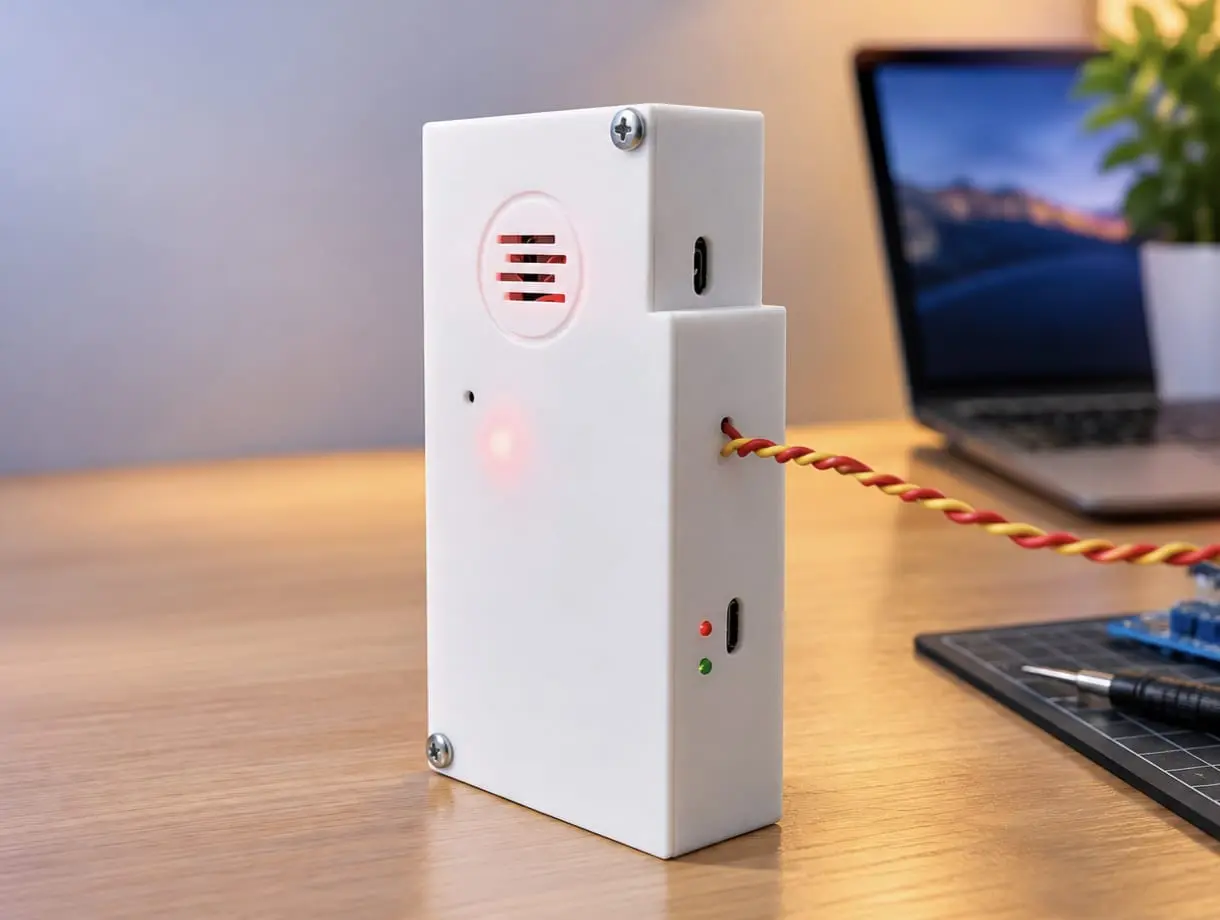
A standalone, voice-responsive smart relay unit engineered around the ESP32 microcontroller and the INMP441 omnidirectional I2S digital microphone. The device provides edge-level acoustic sensing, converting voice commands and acoustic triggers into isolated relay switching actions for home appliances and industrial loads. Designed as a self-contained IoT node, it integrates an onboard 18650 lithium power management system, DC-DC boost regulation, and a custom 3D-printed acoustic enclosure.

Key Technical Features

  • High-Fidelity I2S Digital Audio: Employs the INMP441 MEMS microphone over an I2S digital bus, eliminating analog signal degradation, electromagnetic interference, and pre-amp noise.
  • Real-Time Edge Signal Processing: The ESP32 continuously samples audio buffers, executing digital filtering and Root Mean Square (RMS) energy threshold analysis for instant switching.
  • Galvanically Isolated Switching: Driven by a single-channel 5V electromechanical relay capable of switching both AC mains (up to 250V AC / 10A) and high-current DC loads safely.
  • Autonomous Power Architecture: Powered by an onboard 18650 Li-ion cell paired with a TP4056 USB-C charging/protection circuit and an XL6009 DC-DC boost converter delivering stable 5V rail voltage.
  • Custom Acoustic Enclosure: Dual-section 3D-printed chassis featuring an isolated upper acoustic resonance chamber with protective sound baffles and lower power-stage isolation.

Hardware Architecture

Core Processing & Audio Input

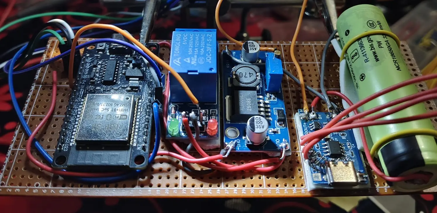
  • ESP32 Dev Module: 240 MHz dual-core Xtensa LX6 processor handling digital I2S sampling, pattern recognition, and GPIO actuation.
  • INMP441 MEMS Microphone: Low-noise, bottom-ported omnidirectional microphone outputting 24-bit digital audio over standard I2S protocol.

Switching & Power Management

  • 5V Relay Module (Tongling JQC-3FF-S-Z): Opto-isolated relay interface handling load switching with onboard status LEDs.
  • 18650 Li-Ion Cell (3.7V / 3300mAh): High-capacity rechargeable power source for untethered wireless deployment.
  • TP4056 Charge & Protection Board: Type-C charging port with over-charge, over-discharge, and short-circuit cutoff.
  • XL6009 Boost Converter: Stepped-up regulated 5V DC output supplying the relay coil and logic circuits.

GPIO Pin Allocation

  • GPIO 25: INMP441 WS (Word Select / Left-Right Clock)
  • GPIO 32: INMP441 SCK (Serial Clock)
  • GPIO 33: INMP441 SD (Serial Data In)
  • GPIO 26: Relay Control Signal (IN)
  • GPIO 2: Red Acoustic Detection / Trigger LED
  • GPIO 4: Green Relay State Indicator LED

Firmware Implementation

The firmware utilizes the native ESP32 I2S driver to sample mono 32-bit audio buffers. It processes raw PCM samples through an RMS calculation engine, comparing amplitude against dynamic thresholds to trigger the relay while enforcing a lockout window to prevent false double-triggers.

cpp
1#include <Arduino.h>
2#include <driver/i2s.h>
3
4// --- Pin Definitions ---
5#define I2S_WS 25
6#define I2S_SCK 32
7#define I2S_SD 33
8
9#define RELAY_PIN 26
10#define LED_TRIGGER 2
11#define LED_STATUS 4
12
13// --- Audio & Trigger Parameters ---
14#define I2S_PORT I2S_NUM_0
15#define SAMPLE_RATE 16000
16#define BUFFER_LEN 512
17#define SOUND_THRESHOLD 250000000 // Amplitude threshold for command detection
18#define TRIGGER_COOLDOWN 800 // Milliseconds lockout between triggers
19
20// State Variables
21bool relayState = false;
22unsigned long lastTriggerTime = 0;
23int32_t audioBuffer[BUFFER_LEN];
24
25void setupI2S() {
26 i2s_config_t i2s_config = {
27 .mode = (i2s_mode_t)(I2S_MODE_MASTER | I2S_MODE_RX),
28 .sample_rate = SAMPLE_RATE,
29 .bits_per_sample = I2S_BITS_PER_SAMPLE_32BIT,
30 .channel_format = I2S_CHANNEL_FMT_ONLY_LEFT,
31 .communication_format = I2S_COMM_FORMAT_STAND_I2S,
32 .intr_alloc_flags = ESP_INTR_FLAG_LEVEL1,
33 .dma_buf_count = 4,
34 .dma_buf_len = BUFFER_LEN,
35 .use_apll = false,
36 .tx_desc_auto_clear = false,
37 .fixed_mclk = 0
38 };
39
40 i2s_pin_config_t pin_config = {
41 .bck_io_num = I2S_SCK,
42 .ws_io_num = I2S_WS,
43 .data_out_num = I2S_PIN_NO_CHANGE,
44 .data_in_num = I2S_SD
45 };
46
47 i2s_driver_install(I2S_PORT, &i2s_config, 0, NULL);
48 i2s_set_pin(I2S_PORT, &pin_config);
49 i2s_zero_dma_buffer(I2S_PORT);
50}
51
52void toggleRelay() {
53 relayState = !relayState;
54 digitalWrite(RELAY_PIN, relayState ? HIGH : LOW);
55 digitalWrite(LED_STATUS, relayState ? HIGH : LOW);
56}
57
58void setup() {
59 Serial.begin(115200);
60
61 pinMode(RELAY_PIN, OUTPUT);
62 pinMode(LED_TRIGGER, OUTPUT);
63 pinMode(LED_STATUS, OUTPUT);
64
65 // Initial safe states
66 digitalWrite(RELAY_PIN, LOW);
67 digitalWrite(LED_TRIGGER, LOW);
68 digitalWrite(LED_STATUS, LOW);
69
70 setupI2S();
71 Serial.println("Voice Relay Node Initialized. Listening...");
72}
73
74void loop() {
75 size_t bytesRead = 0;
76 esp_err_t result = i2s_read(I2S_PORT, &audioBuffer, sizeof(audioBuffer), &bytesRead, portMAX_DELAY);
77
78 if (result == ESP_OK && bytesRead > 0) {
79 int samplesRead = bytesRead / sizeof(int32_t);
80 int64_t sumEnergy = 0;
81
82 for (int i = 0; i < samplesRead; i++) {
83 // INMP441 provides 24-bit data MSB-aligned in 32-bit slot
84 int32_t sample = audioBuffer[i] >> 14;
85 sumEnergy += (int64_t)sample * sample;
86 }
87
88 int64_t meanEnergy = sumEnergy / samplesRead;
89
90 // Acoustic threshold evaluation
91 if (meanEnergy > SOUND_THRESHOLD) {
92 unsigned long currentTime = millis();
93 if (currentTime - lastTriggerTime > TRIGGER_COOLDOWN) {
94 lastTriggerTime = currentTime;
95
96 // Visual feedback pulse
97 digitalWrite(LED_TRIGGER, HIGH);
98 toggleRelay();
99
100 Serial.printf("Voice Trigger Detected! Energy: %lld | Relay: %s\n",
101 meanEnergy, relayState ? "ON" : "OFF");
102
103 delay(100);
104 digitalWrite(LED_TRIGGER, LOW);
105 }
106 }
107 }
108}